

Skip to content

C.R. 1294141 · Salalah, Dhofar Governorate

Method statements

How the workis done.

The company profile contains written method statements for each work type. They are condensed here with their objective, materials, equipment, sequence and records, in the order they appear in the profile.
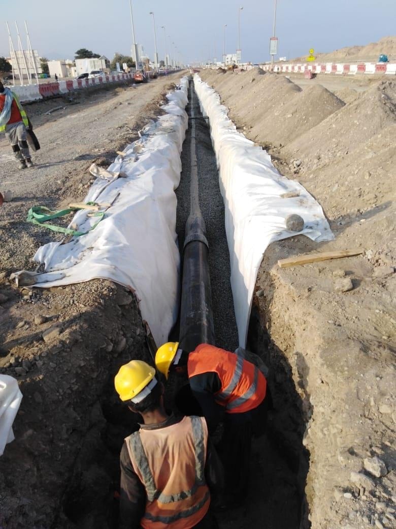
Crew working in a lined trench
Line-ditch construction

Project management

Project Quality Plan and mobilisation procedure

Source: profile pp12-17

Control of project implementation from award of tender to handover, through the Project Quality Plan (PQP) with Inspection and Test Plans (ITPs) and work instructions where their absence would affect quality.

  1. 01

    Possession of site

    Boundary points identified with the local authorities; perimeter pegs cemented and reference points fixed; coordinates and point-to-point distances verified; obstructions and existing services recorded.

  2. 02

    Contract documents

    Three sets of valid construction drawings, the contract specifications and the ratified contract documents received and recorded.

  3. 03

    Manpower

    Technical manpower for specific trades and key project staff mobilised from head office; general labour recruited with government approvals; specialist trades such as asphalt considered for sub-contract.

  4. 04

    Machinery

    Plant mobilised from the joint partnership’s own resources, which include an in-house plant-maintenance department; new equipment purchased where necessary.

  5. 05

    Site establishment

    Mobilisation completed within 21 days, including labour force, plant, site offices, workshops and stores in portable cabins; generators used until temporary power connections are provided.

  6. 06

    Work instructions

    Prepared where the importance, complexity, quality history or operator experience of an operation requires them.

  7. Records: Project Quality Plan · Inspection and Test Plans · Work instructions · Progress reports at contractual intervals · Post-award and periodic contract reviews

Roads

Road construction methodology

Source: profile pp83-87

Construct the road to the requirements of the contract: preliminary works, survey and design; clearing and grubbing; roadway excavation; borrow materials; excavation and backfill for structures; granular sub-base, aggregate base course and stabilised course; bituminous pavement; concrete structures and rigid pavements; drainage; slope protection; traffic signs and road markings; future utility ducts; traffic management.

Equipment

  • Graders, dozers, JCBs, loaders and tippers
  • Excavators and rock breakers
  • Rollers and water tankers
  • Screen plant and mobile screen plant
  • Hiab and JCB for signposts
  1. 01

    Pre-execution

    Excavation permits obtained from statutory authorities; borrow pits identified; contractor’s and Engineer’s facilities established during mobilisation.

  2. 02

    Survey

    Control points located and protected; working control points established along the alignment and verified by the Engineer; joint survey with cross-sections at 20 m intervals.

  3. 03

    Design and shop drawings

    Roads and structures designed from survey and hydrological data and submitted for approval; shop drawings show alignment, profile and cross-sections to calculate cut and fill.

  4. 04

    Clearing and grubbing

    Vegetation, roots and debris removed with grader, dozer, JCB, loaders and tippers under a foreman and grader team.

  5. 05

    Excavation

    Cut material tested for suitability; suitable material used on the nearest embankment, unsuitable material disposed of at approved locations.

  6. 06

    Foundation preparation

    Top 200 mm scarified, watered, mixed, graded and compacted with a ripping grader, roller and water tanker.

  7. 07

    Embankment

    Fill placed, spread, graded, moistened and compacted in layers; rock fill up to 80 cm tested by plate test; normal fill tested to AASHTO T 180 Method D at ±1.5% of optimum moisture; 90% MDD for embankment and 95% for subgrade.

  8. 08

    Sub-base and base course

    250 mm granular sub-grade and 200 mm class B sub-base; own screen plant for gradation; mix design, plant trial and field trial approved by the Engineer; vibratory rolling until uniform compaction.

  9. 09

    Concrete structures

    Shop drawings and bar-bending schedules to the highway design manual; design mixes approved; culverts cast in situ or precast and cured seven days; no traffic on box culverts without 300 mm cover; inlets and outlets cleared.

  10. 10

    Signs and markings

    Precast sign foundations; shop drawings for locations and Arabic/English text; posts painted, offset and verticality checked; installed by foreman with Hiab and JCB.

Protection & concrete

Cut-off wall (1.2 m) and protection works

Source: profile p18

Construction of a 1.2 m cut-off wall and installation of mortared riprap to provide erosion control.

Materials

  • Cut-off wall steel and concrete
  • Bituminous paint

Equipment

  • Excavators
  • Bentonite mixing and pumping equipment
  • Concrete mixers and vibrators
  • Surveying instruments
  • Safety equipment
  1. 01

    Site preparation

    Area cleared of obstructions; alignment and dimensions of the wall established.

  2. 02

    Excavation

    Trench excavated to 1.2 m or 1.6 m with stable walls free of loose material.

  3. 03

    Installation

    Wall material and steel reinforcement installed to design with proper overlap between sections.

  4. 04

    Backfill

    Trench backfilled with excavated or specified material and compacted in layers to the required density.

  5. 05

    Quality control

    Checks during and after installation and testing of wall integrity.

Class 30 concrete floodway protection slab

Source: profile pp19-20

Construction of reinforced Class 30 concrete floodway protection slabs.

Materials

  • Concrete Class 30 to the approved mix
  • Reinforcement where specified
  • Formwork, release agents, joint materials, curing compounds

Equipment

  • Concrete mixers, pump or transport vehicles
  • Vibrators, screeds, bull floats, trowels
  • Formwork supports
  • Surveying equipment
  1. 01

    Site preparation

    Site cleared; area excavated and shaped to design dimensions.

  2. 02

    Formwork

    Set to dimensions with proper alignment and bracing; release agent applied.

  3. 03

    Reinforcement

    Installed where specified according to the design.

  4. 04

    Concrete

    Class 30 mixed to the approved design, placed, consolidated with vibrators, screeded and floated.

  5. 05

    Finishing and curing

    Surface trowelled to specification; construction joints installed where required; curing compound applied and the slab protected from adverse weather.

High-tensile steel bar reinforcement

Source: profile pp20-21

Fabrication and placement of high-tensile reinforcement of any diameter.

Materials

  • High-tensile steel bars
  • Tie wires, spacer blocks and chairs
  • Stirrups and links to design

Equipment

  • Bar bending and cutting machines
  • Tying tools
  • Concrete mixers and vibrators
  1. 01

    Bending and cutting

    Bars bent and cut accurately to the shop drawings.

  2. 02

    Placement

    Bars placed to the approved shop drawings with cover and spacing maintained by spacers and supports.

  3. 03

    Tying

    Bars tied at all intersections and overlaps to the specified pattern.

  4. 04

    Inspection

    Placement, alignment and tying inspected at stages and discrepancies rectified before concreting.

Bituminous paint application

Source: profile pp21-22

Protective bituminous coating of concrete surfaces.

  1. 01

    Surface preparation

    Surface cleaned, dried and repaired; primer applied where specified.

  2. 02

    Mixing

    Paint mixed to a uniform consistency.

  3. 03

    First coat

    Applied evenly by brush, roller or spray to full coverage and allowed to dry.

  4. 04

    Second coat

    Surface inspected and touched up, then second coat applied and dried thoroughly.

Loose and mortared stone riprap

Source: profile pp22-24

Installation of loose stone riprap and mortared stone riprap for slope and channel protection.

Materials

  • Riprap stones of specified size
  • Geotextile and filter fabric
  • Mortar mix to specification
  • Reinforcement and bonding agents where specified

Equipment

  • Excavators, front-end loaders and dump trucks
  • Concrete and mortar mixers
  • Masonry and hand tools
  • Surveying equipment
  1. 01

    Preparation

    Site cleared; area excavated and shaped; geotextile and filter fabric placed with overlap and secured.

  2. 02

    Loose riprap

    Stones placed from the toe upward so they interlock, to the specified thickness and slope; voids filled and the layer compacted with vibratory rollers.

  3. 03

    Mortared riprap

    Surface wetted; mortar applied to the base of each stone and stones set in a systematic pattern; joints filled, tooled and finished.

  4. 04

    Curing and cleaning

    Work protected during the curing period; excess mortar cleaned promptly.

Gabions, 500 mm and 1000 mm

Source: profile pp24-25

Installation of gabion baskets for embankment and channel protection.

Materials

  • Gabion baskets to the specified mesh
  • Geotextile and filter fabric
  • Stones of specified size
  • Lacing wire
  1. 01

    Preparation

    Site cleared and shaped; geotextile placed at the base and secured.

  2. 02

    Assembly

    Baskets assembled to manufacturer’s specifications and placed in alignment.

  3. 03

    Filling

    Baskets filled with the specified stone, compacted so stones interlock.

  4. 04

    Lacing and compaction

    Mesh laced and closed securely; voids between gabions filled and the structure compacted.

Building & finishing

Plaster works

Source: profile pp26-29

Internal and external plastering of concrete and blockwork surfaces to a smooth, dense finish ready for paint or wall covering.

Materials

  • Plaster accessories, angle beads, coil lath and expanded mesh
  • Rush coat for concrete surfaces
  • Render for concrete and blockwork
  • Clean potable water

Equipment

  • Straight edges and measuring tapes
  • Mechanical mixers
  • Certified scaffolding above 1.5 m
  1. 01

    Setting out

    Reference points and levels confirmed; key pads fixed at 2.5 m minimum for alignment, thickness and plumb; sub-frames fixed to approved anchors.

  2. 02

    Coordination

    No plaster on any wall until cleared; architectural, wooden sub-frame, mechanical and electrical works complete with MEP clearance; areas free of excessive moisture.

  3. 03

    Accessories

    Angle beads on all external angles, anchored at 300 mm centres; coil lath 200 mm wide at dissimilar substrates; mesh at RCC-to-blockwork joints.

  4. 04

    Surface preparation

    Irregularities filled 24 hours before; concrete surfaces cleaned and wetted; rush coat applied and cured two days.

  5. 05

    Execution

    Inspection request raised for accessories, dots and bands; plaster applied by professional masons, stopped at beads or grooves; over 15 mm applied in two coats; corners sharp; straight-edge and plumb-bob checks; cured two days.

  6. 06

    Patching and cleaning

    Cracks and debonded areas checked after curing and patched to match; surfaces cleaned and debris removed before final inspection.

  7. Records: Inspection request before and after plastering

Internal and external painting

Source: profile p29

Painting of plastered walls (cement mix 1:5) internally and externally.

  1. 01

    Preparation

    External walls washed and foliage cut back; two coats of wall putty to level undulations, POP where major; 10–12 hours drying.

  2. 02

    Smoothing and primer

    Surfaces smoothed with 220-grit sandpaper; one coat of primer, 3–4 hours drying.

  3. 03

    Paint

    Two coats of paint, each left 10–12 hours to dry.

Wooden cladding, doors, windows, glass and false ceilings

Source: profile pp30-33

Fit-out items for a restaurant building: wooden cladding, glass works, false ceiling, wooden doors D1 and D2, aluminium windows W1, V1 and V2, sanitary fittings, steel staircase, benches, granite pantry counter and flag pole.

  1. 01

    Wooden cladding

    Moisture barrier fixed to plywood from the bottom up with overlaps; starter plank scribed level; tongue-and-groove planks blind-nailed with stainless steel nails; mitred corners, trim, caulk, stain and seal.

  2. 02

    False ceiling

    Height marked around the room; framework fixed to beams or suspended; struts and wall supports fixed; insulation applied; panels fixed and joints finished.

  3. 03

    Aluminium windows

    Blinds and architraves removed and floors protected; opening prepared; window lifted into the recess, levelled, drilled and fixed; architraves and storm moulds reinstated; rot, sill bricks and rendering addressed if found.

  4. 04

    Doors and sanitary items

    Wooden doors D1 and D2, wash basins and water closets installed with all fittings to specification.

  5. 05

    Steel staircase and furniture

    Members measured, cut and welded or bolted; stringers, treads, risers, handrails and balusters fitted; benches built to drawing and finished; granite pantry counter measured, selected and installed.

  6. 06

    Flag pole

    Working area coned off; foundation dug and the hinged base or ground socket set in the hole.

Maintenance of an agriculture unit, Mirbat

Source: profile pp34-36

Renovation for the Ministry of Agriculture, Fisheries Wealth and Water Resources: preliminary works, civil works, removals, painting, plastering, tiling and plumbing.

  1. 01

    Removals

    Old wooden and aluminium doors and windows with grids removed; concrete sinks demolished; an existing 3.5 × 2.5 m wall demolished to merge rooms as indicated by the Ministry.

  2. 02

    Civil works

    Openings closed with 10 mm hollow block, plastered and painted to match; new openings formed for doors and an exhaust fan.

  3. 03

    Finishes

    Wall and floor tiles supplied and fixed to match existing; damaged tiles replaced.

  4. 04

    Doors and windows

    UPVC doors and windows with grids and blinds supplied and fixed as approved.

  5. 05

    Services

    Drainage pipes redirected; LED lights, a 6-inch exhaust fan and 13 A socket outlets installed as approved.

Electrical & street lighting

Installation of transformer package substation

Source: profile pp148-151

General methods for the installation of a transformer package substation including foundation civil works, under an Electrical Engineer, Foreman and HSE Officer.

Equipment

  • Cable detector
  • Insulated hand tools
  • Truck with crane (Hiab) and lifting slings
  • Excavators / JCB and compactor
  • Lineman and cable-jointer toolkit
  • Testing equipment with valid calibration
  1. 01

    Pre-installation checks

    Location identified and permissions acquired; ground level checked; lookout arrangements before crane operation; slings checked for working load; material inspected for damage; nameplates and test certificates checked; foundation suitability and crane capacity confirmed.

  2. 02

    Sequence

    Transformer position marked; oil filled in a dry, clean atmosphere; transformer lifted using all hooks with balance ensured; placed on the basement and rechecked; installation inspected for damage.

  3. 03

    Testing

    IR tests on LV and HV sides; hi-pot test on the cable between RMU and transformer with IR before and after; earthing provided; terminals discharged after each reading.

  4. 04

    HSE

    Toolbox talk on PPE, evacuation, emergency and communication arrangements; hi-pot test area barricaded and restricted to authorised persons; risk assessment submitted.

  5. Records: Quality check lists · Marked-up drawings · Inspection forms (RFI) · As-built drawings

Installation of feeder pillars

Source: profile pp152-156

Ensure that feeder-pillar installation, on-site assembly, final connection and workmanship conform to the contract documents and specification.

Equipment

  • Insulated hand tools
  • Truck with crane (Hiab), forklift and lifting slings
  • Steel pipe rollers
  • Lineman and cable-jointer toolkit
  • Testing equipment
  1. 01

    Storage

    Pillars unloaded to a designated area by forklift or mobile crane and stored dry, clean and safe.

  2. 02

    Pre-installation

    Materials and documentation checked; locations accessible, clean and suitable.

  3. 03

    Sequence

    Cable trenches and supports painted and ready; crated pillars lifted under the sub-base; uncrated and moved on pipe rollers; aligned horizontally and vertically and secured to the base; covers and doors refitted.

  4. 04

    Testing

    Insulation-resistance test on the pillar; request for inspection raised; cable dressing and termination after consultant sign-off.

  5. 05

    HSE

    Toolbox talk including fire-extinguisher use; winch checked before use; cable trenches signed, taped and barricaded until backfilled.

  6. Records: Quality check lists · Inspection forms (RFI) · As-built drawings

Installation of street-light system

Source: profile pp157-159

Ensure that street-light pole assembly, erection, final electrical connection and workmanship conform to the contract documents and specification.

Equipment

  • Insulated hand tools
  • Truck with crane (Hiab) or crane as approved, with lifting slings
  • Trucks and pick-ups
  • Lineman and cable-jointer toolkit
  • Testing equipment
  1. 01

    Storage

    Street-light materials unloaded to a designated area and stored dry and clean.

  2. 02

    Pre-installation

    Materials and documentation checked; locations accessible and free of debris.

  3. 03

    Erection

    Foundations checked against approved drawings; pole accessories assembled to the manufacturer’s manuals; pole erected by Hiab or crane; foundation-bolt nuts fixed and alignment checked.

  4. 04

    Connection and commissioning

    Request for inspection raised; after sign-off, cable connection completed and testing and commissioning performed.

  5. 05

    HSE

    Toolbox talk before each activity; daily PPE checks; winch checked; open trenches signed and barricaded; risk assessment submitted.

  6. Records: Quality check lists · Inspection forms (RFI) · As-built drawings

Personal protective equipment common to these statements

  • Ear protection, muffs or plugs, where required
  • Helmet / hard hat
  • Hand gloves, rubber or cotton
  • Dust mask (respiratory protection) where required
  • Splinter-proof safety glasses
  • Safety belts / harness where required
  • Safety shoes
  • Overalls

Start a conversation

Let’s buildwhat comes next.

Send us the drawings, bill of quantities or a first description of the works. Our office in Salalah will respond with a clear view on scope, resources and programme.